Menu
$ AUD
-
$ AUD
-
$ NZD
-
$ USD
-
€ EUR
-
$ CAD
-
د.إ AED
-
$ ARS
-
R$ BRL
-
£ GBP
-
Ft HUF
-
₹ INR
-
kr. ISK
-
KSh KES
-
RM MYR
-
K PGK
-
₲ PYG
-
₱ PHP
-
zł PLN
-
₽ RUB
-
R ZAR
-
฿ THB
-
₺ TRY
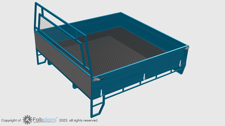


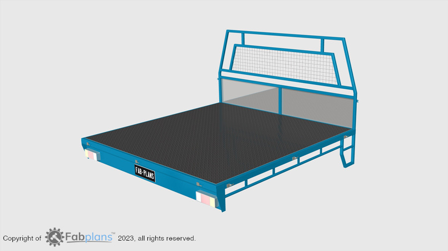


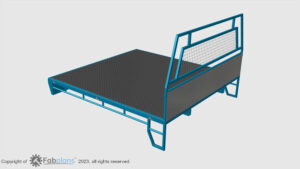
If you are looking to save money or just need something stronger than a mass produced/imported pickup tray, our steel tray plans provide every detail and dimension you need to be able to build your own high strength, long lasting tray to complement your vehicle.
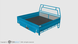
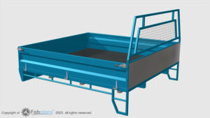
These plans will suit any space cab or extra cab ute, they feature a sliding chassis mounting system that allows you to adjust the mounting position to suit your vehicle before fixing in place and can be refitted to any other vehicle so you can keep the tray when you upgrade!
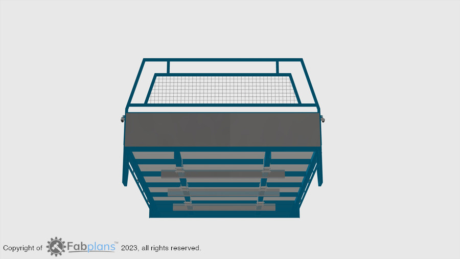
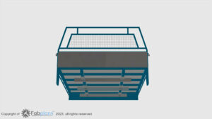
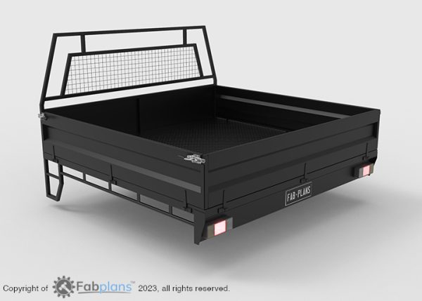
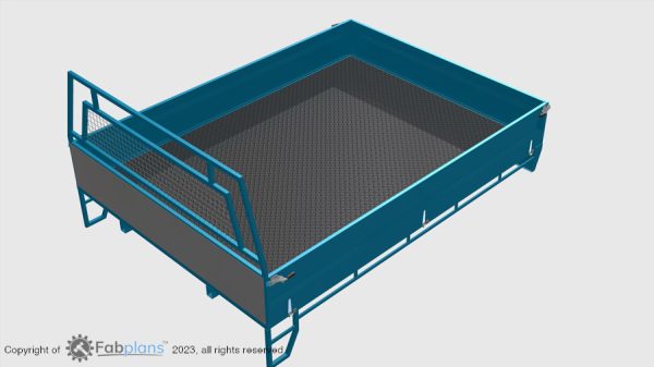
The plans feature quick release removable sides allowing either flatbed or enclosed tray configuration. Side steps on both sides allow easy climbing access to the tray or an additional tie down point.
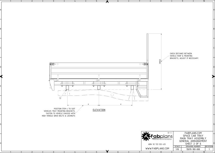
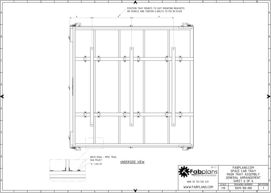
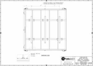
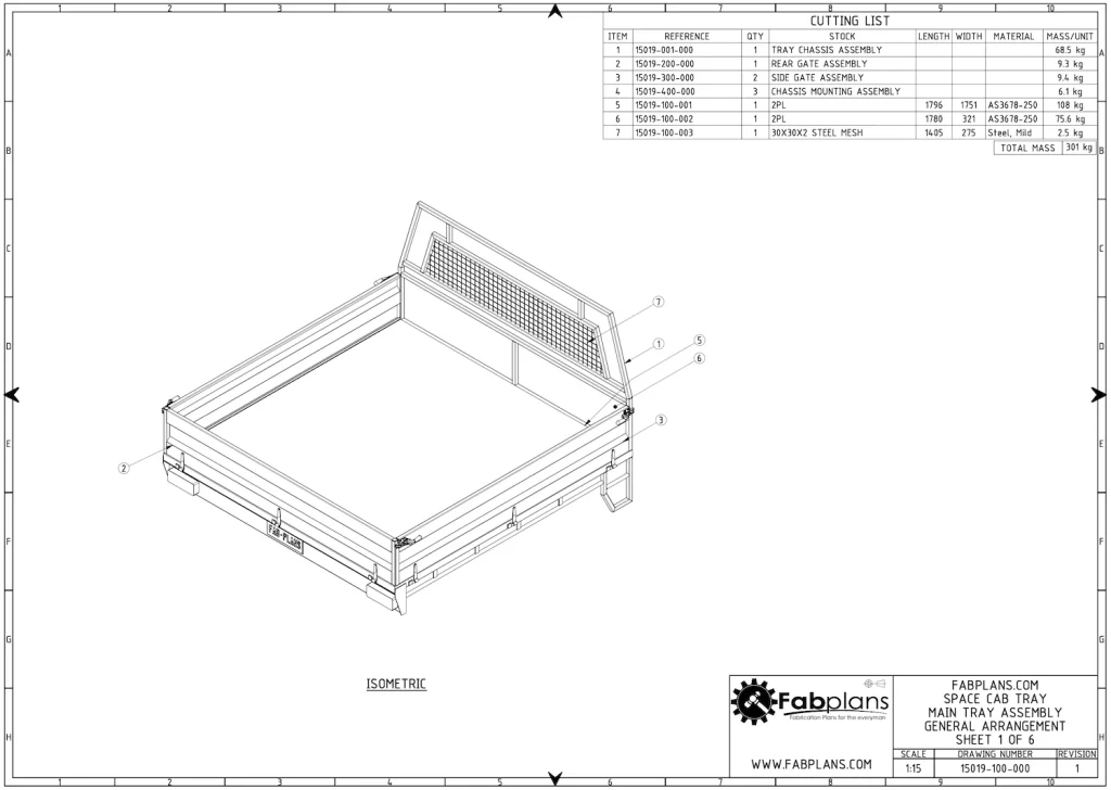
Throughout the 29 pages the plans cover all general arrangement views showing: where each part goes, lengths and material type, all dimensions and, a number of section and detail views showing close up features of smaller parts.
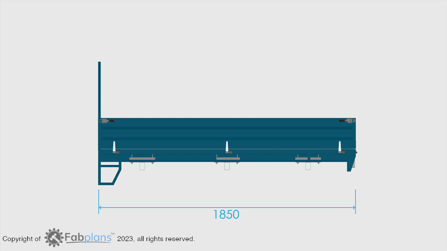
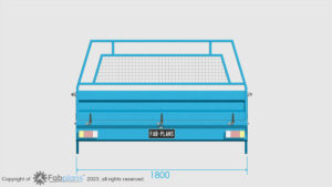
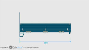
| Tray size: | 2500mm (L) x 1800mm (W) | 8.2ft x 5.9ft |
| Tray depth: | 300mm | 1ft |
| Tray weight: | 350kg | 772lbs |
| File sizes: | PDF | 3 MB (.pdf) | DXF | 503 KB (.zip) |
All our plans are designed to be easy-to-follow allowing just about anyone to tackle their own build. That being said, not all fabrication tasks are equal. Some will require you to use tools that the home workshop may not have.
Fabrication skill level: Basic.

ESTIMATED BUILD TIME:
2 weekends
This plan set comes with 29 pages of detailed drawings to help guide you through your build.
The plans are broken down into four assemblies:
Included are part lists which help you identify what is required for each section of the build.
Once you have purchased a set of plans, you are invited to join our Private Facebook Group. Here you can share your build and get help from other fabricators who have done it all before! We want you to have the support you need to not just start, but to finish your trailer or ute tray build.
Reviews
There are no reviews yet